Using Counter and Timer Control
Subject
Technical Application Note: Using Counter and Timer Control
Applicable Products
- Blackfly S
- Oryx
Application Note Description
This document provides an overview of the Counter and Timer Control feature in the Blackfly S and Oryx cameras.
Introduction
The Counter and Timer feature allows you to:
- Create a function generator
- Keep a count of how many times a signal has fired
Some general applications include:
- Input to Logic Block
- Line output for controlling external devices
- Keep track of how many times the camera has exposed
- Keep track of how many times an external input signal has triggered
- Trigger the camera at a predefined period of time
Note: This document uses the SpinView application to demonstrate the configuration and execution of Counter and Timer Control.
Configuring Counter and Timer Control
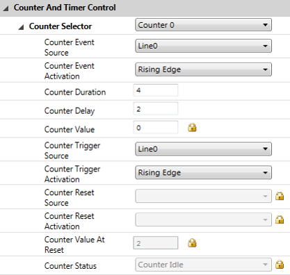
- Select the counter (0 or 1).
- Select Event Source to indicate when the counter increments.
- When the selected source allows for signal activation, use Counter Event Activation to specify Level Low, Level High, Falling Edge, Rising Edge, or Any Edge.
- Set the Counter Delay to indicate the maximum number of counts that need to occur before generating the Counter Start event.
- Set the Counter Duration to indicate the maximum number of counts that need to occur before generating the Counter End event.
- Select either the Counter Trigger Source to specify the event to start the counter or Counter Reset Source to specify the event to restart the counter. Only one can be active at a time. Selecting one disables the other.
- Select the Counter Trigger Source.
- When the selected source allows for signal activation, use Counter Trigger Activation to specify Level Low, Level High, Falling Edge, Rising Edge, or Any Edge.
OR
- Select the Counter Reset Source.
- When the selected source allows for signal activation, use Counter Reset Activation to specify Level Low, Level High, Falling Edge, Rising Edge, or Any Edge.
Possible sources for event, trigger, or reset include:
- MHz Tick
- Line Inputs
- User Outputs
- Counter Starts
- Counter Ends
- Logic Block Outputs
- Exposure Start
- Exposure End
- Frame Trigger Wait
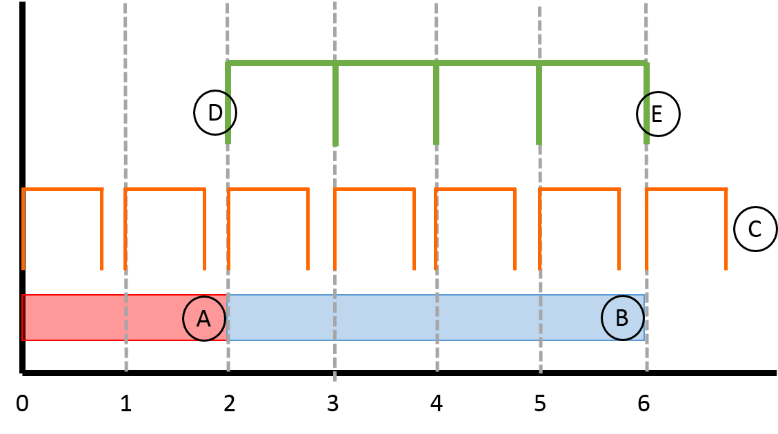
Example
The counter increments by 1 on every rising edge at Line0 to a maximum of 4.
Counter Status
Counter status can be queried from the nodemap as either Active or Idle.
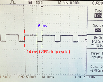
Pulse Width Modulation Example
The goal of this example is to strobe a 50 Hz pulse with 70% duty cycle.
Step 1 - Set up the GPIO Connection
The first step is to set up the hardware to output the PWM signal from the camera. For this example, we use an oscilloscope to display the signal. The GPIO pins vary depending on the camera family used.
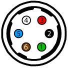
Blackfly S (BFS)
BFS cameras have a 6-pin GPIO. It has both a non-isolated output and an opto-isolated output. If using the opto-isolated output (as in our example) the camera requires a pull-up resistor to strengthen its strobe signal.
| Diagram | Color | Pin | Line | Function | Description |
|---|---|---|---|---|---|
|
|
Green | 1 | 3 | VAUX | Auxiliary Input Voltage (DC) |
| GPI | Non-isolated Input | ||||
| Black | 2 | 0 | OPTOIN | Opto-isolated Input | |
| Red | 3 | 2 | VOUT | Camera Power Output | |
| GPIO | Non-isolated Input/Ouput | ||||
| White | 4 | 1 | OPTOOUT | Opto-isolated Output | |
| Blue | 5 | N/A | Opto GND | Opto-isolated Ground | |
| Brown | 6 | N/A | GND | Camera Power Ground |
To configure the BFS camera's strobe output:
- Connect the camera's pin 4 (white wire, opto-isolated output) to the oscilloscope's input connection for channel 1.
- Connect the primary camera's pin 5 (blue wire, opto-isolated ground) to the oscilloscope's ground connection for channel 1.
To configure the pull-up resistor needed to strengthen the signal:
- Connect one end of a 10 kΩ resistor to the camera's pin 3 (red wire, 3.3 V output).
- Connect the other end of the resistor to the camera's pin 4 (white wire, opto-output).
- Connect the camera's pin 6 (brown wire, ground) to the camera's pin 5 (blue wire, opto-ground).
Oryx (ORX)
Oryx cameras have a 12-pin GPIO. It has two non-opto pins that can be used as either input or output. Non-opto pins do not need a pull-up resistor to strengthen the strobe signal. This example uses the non-opto pins.
| Color | Pin | Line | Function | Description | |
|---|---|---|---|---|---|
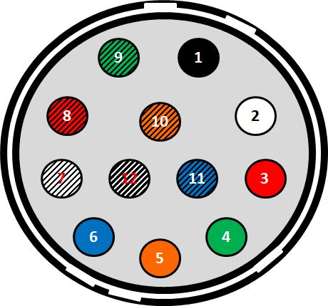 |
Black | 1 | N/A | GND | DC camera power ground |
| White | 2 | N/A | POWER | DC camera power | |
| Red | 3 | Line 1 | GPIO_OPT_OUT1 | Opto-isolated output (GPO1) | |
| Green | 4 | Line 4 | GPIO_OPT_OUT2 | Opto-isolated output (GPO2) | |
| Orange | 5 | Line 0 | GPIO_OPT_IN1 | Opto-isolated input (GPI1) | |
| Blue | 6 | Line 3 | GPIO_OPT_IN2 | Opto-isolated input (GPI2) | |
| White/black stripes | 7 | Line 2 | GPIO_TTL_IO3 | TTL input/output 3* | |
| Red/black stripes | 8 | Line 5 | GPIO_TTL_IO4 | TTL input/output 4* | |
| Green/black stripes | 9 | N/A | GND | DC camera power ground | |
| Orange/black stripes | 10 | N/A | POWER | DC camera power | |
| Blue/black stripes | 11 | Line 6 | 3.3 V OUTPUT | +3.3 V output, current 120 mA (nominal) - firmware enabled | |
| Black/white stripes | 12 | N/A | OPTO_GND | Ground for opto-isolated I/O, not connected to camera ground | |
| *When configured as output line format is open drain, not TTL. Users should attach their own external pull-up resistor. | |||||
To configure the ORX camera's strobe output:
- Connect the camera's pin 7 (white with black stripes wire, output) to the oscilloscope's input connection for channel 1.
- Connect the camera's pin 9 (green with black stripes wire, ground) to the oscilloscope's ground connection for channel 1.
Step 2 - Set up the software (SpinView)
The steps below show how to set up the PWM signal in SpinView.
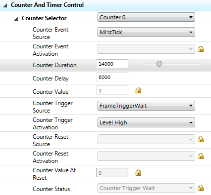
1. Select a Counter (either 0 or 1).
2. From Counter Event Source, select MHz Tick which is a signal of 1 MHz.
3. To create a 50 Hz clock, we need a counter duration of 20,000.
| 1 MHz / 50 Hz = | 20,000 cycles / duration |
4. Define Counter Duration and Counter Delay values to create a 70% duty cycle.
| Counter Delay = | 30% x 20,000 = | 6,000 |
| Counter Duration = | 70% x 20,000 = | 14,000 |
5. From Counter Trigger Source, select FrameTriggerWait. Set Counter Trigger Activation to Level High.
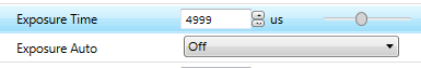
6. Disable Exposure Auto and set an Exposure Time of less than 1/50 second.
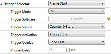
7. Enable Trigger Mode and select Trigger Source to Counter0 Start.
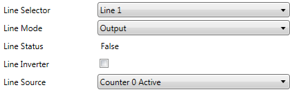
8. Configure GPIO so that Line 1 is in Output mode and the Line Source is Counter 0 Active. For ORX cameras, use Line 2.
9. For BFS cameras only, enable the 3.3 V line (red wire).
- From the Line Selection drop-down, select Line 2.
- Select 3.3V Enable.
10. Start streaming.
Detect Missing Trigger Example
The goal of this example is to detect missing triggers.
Missing Triggers = Total Number of Triggers – Total Number of Exposures
Counter0 counts the total number of triggers. Counter1 counts the total number of exposures.
1. Disable Exposure Auto and set a long Exposure Time (for example, 3.5 seconds).
2. Enable Trigger Mode and set Trigger Source to line 0 Rising Edge.
3. Connect Line0 (1 Hz TTL signal) to the camera.
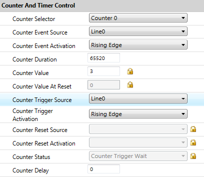
4. Configure Counter0 to count the number of triggers.
a. From Counter Event Source, select Line0. Set Counter Event Activation to Rising Edge.
b. From Counter Trigger Source, select Line0. Set Counter Trigger Activation to Rising Edge.
c. Set the Counter Duration to a high value and Counter Delay to 0.

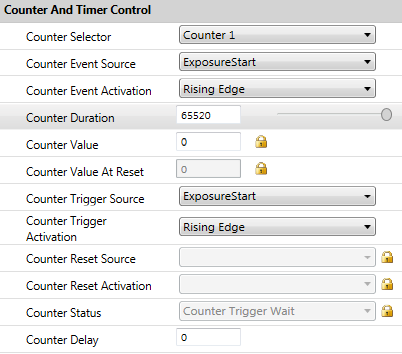
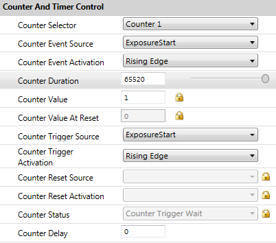
5. Configure Counter1 to count the number of exposures.
a. From Counter Event Source, select ExposureStart. Set Counter Event Activation to Rising Edge.
b. From Counter Trigger Source, select ExposureStart. Set Counter Trigger Activation to Rising Edge.
c. Set the Counter Duration to the same high value as Counter0 and Counter Delay to 0.
6. Enable 1 Hz trigger source. The camera starts capturing images.
7. Right click SpinView GUI to refresh the nodemap and update the Counter Value.
a. Select Counter0 and take note of the Counter Value.
b. Select Counter1 and take note of the Counter Value.
8. Calculate missing triggers:
| Missing trigger = | Counter0 Value – Counter1 Value |
| = | 3 – 1 |
| = | 2 |
Zugehörige Artikel
-
 Anwendungsbericht
ÖLLAGERBETREIBER VERLÄSST SICH BEIM BRANDSCHUTZ SEINES 160 HEKTAR GROSSEN BETRIEBSGELÄNDES AUF FLIR
Bericht lesen -
 Sonstige
a50-a70 Formularseite zum Kontaktieren eines Experten
Bericht lesen -
 Fallstudie
Die Radiometrischen Wärmebildkameras Von FLIR Schützen Ecologica Tredi Gegen Brände
Bericht lesen